Introduction to MEAN WELL First DALI-2 Controller: DLC-02
By: Jay Liang/Technical Service Center
Lxj7343@meanwell.com.cn
With the continuous development of the LED lighting industry, smart lighting has become a standard feature in the smart home market. With DALI (digital addressable lighting control interface), an open protocol, products from different manufacturers are compatible with one another, allowing users to build a comprehensive and coordinated lighting system. How to effectively integrate the lighting system of smart homes is the goal for major manufacturers. Foreseeing the future development needs, MEAN WELL has launched the first lighting system controller, DLC-02, which complies with DALI-2 regulation.
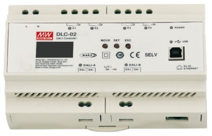
Fig1. DLC-02 model
The DALI system comprises three parts: Bus Power Supply, Control Device and Control Gear. The control devices include input devices and application controllers. Complying with the latest DALI-2 controller (Control device-Part 103) standard, the DLC-02 are built-in two independent DALI power supplies (each providing 250mA current), which can be used as a bus power supply and application control in the DALI system. With the DLC-02, only the input device and control device remain to complete a DALI system.
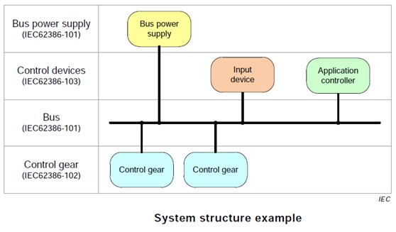
Fig2. DALI-2 System structure example
Input devices include a DALI master, sensors, and control panels, parsing environmental information or personnel operation information into DALI commands and forwarding them to the DALI bus. After the application controller receives the commands on the DALI bus, the corresponding control device is executed, such as different scenes, color temperature, illuminance change adjustment and control of exhaust fans, curtains and other electrical equipment. DALI divides the following types of control devices (Control gear) according to different application functions and fields.
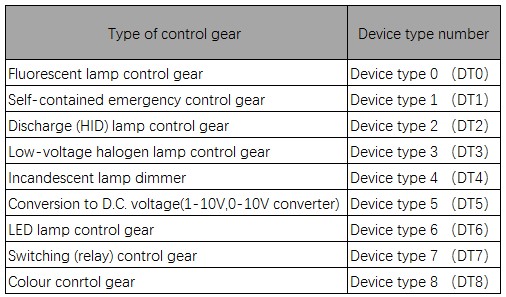
Tbl1. Types of control gears
An indoor office lighting system case with DLC-02:
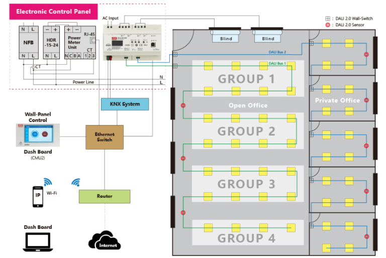
Fig3. An indoor office lighting system
All input devices and control gears on the DALI bus are addressable through DLC software or Web interface (need to be on the same LAN as DLC-02). Each lighting figure can be assigned to corresponding groups or a new group based on user desire. The parameters may then be specified, and the logical relationship between the panel switch, sensor and light control can be built. At the same time, the built-in relays on the DLC-02 can be utilized to control a shutter switch.
Main function settings:
● The panel switch action setting has three options: one-click, two-click and long-press. Each operation, such as one click to turn on and off the lamp and long-press to modify the lamp's brightness, can be set to activate the relevant scenes.
● When the sensor detects movement in the sensing region, the lights in that area will be automatically switched on, or brightness will be adjusted to the appropriate illuminance based on the brightness on-site. When the individual leaves the sensor range, the lights will be automatically dimmed or turned off.
● The DLC-02 is built-in with a timer chip that can set timing action events based on different conditions, such as adjusting or turning off the brightness of all the lamps on the DALI bus during lunch break weekdays. Users may configure Timer's setting functions on the DLC program, such as action time, single or loop settings.
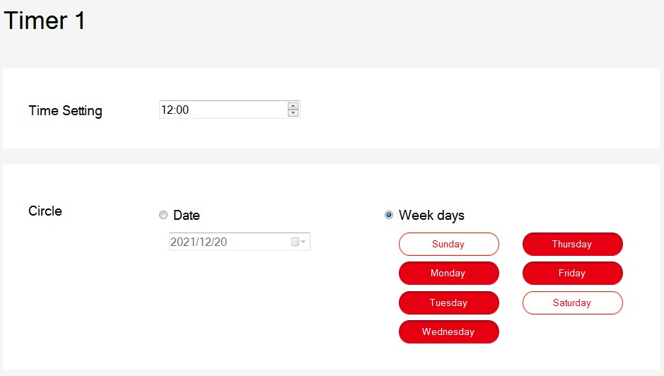
Fig4. Timer setting
